How Marine Shaft Alignment Equipment Works: A Complete Guide
Marine shaft alignment equipment is used to measure and adjust the position of propulsion shafts in ships and other marine vessels.
Proper shaft alignment helps maintain the intended relationship between the engine, gearbox, bearings, stern tube, and propeller while the propulsion system is operating.
Marine propulsion shafts can be long, heavy, and affected by hull deformation, temperature changes, bearing positions, and operating loads. Alignment equipment provides measurements that help engineers determine shaft position and identify deviations from the specified alignment condition.
What Is Marine Shaft Alignment Equipment?
Marine shaft alignment equipment includes measurement instruments, sensors, fixtures, software, and supporting tools used to assess the geometric position of propulsion shafts and related components.
A typical alignment system may be used to evaluate:
- Shaft centerline position
- Shaft offset
- Shaft angularity
- Bearing position
- Coupling alignment
- Flange alignment
- Propeller shaft position
- Gearbox and engine relationship
Modern systems can use optical or laser measurement technologies, while conventional approaches may use dial indicators, feeler gauges, optical instruments, and mechanical measurement tools.
Why Shaft Alignment Matters in Marine Propulsion
The propulsion shaft transfers rotational power from the engine or gearbox to the propeller. Misalignment can change how loads are distributed across bearings, couplings, and other components.
Alignment inspection can help identify conditions associated with:
- Uneven bearing loads
- Coupling stress
- Excessive vibration
- Shaft bending
- Bearing wear
- Seal problems
- Increased mechanical loading
The acceptable alignment condition depends on vessel design, shaft dimensions, bearing arrangement, propulsion equipment, and engineering specifications.
How Marine Shaft Alignment Equipment Works
1. Establishing a Reference
The first step is establishing a reference line or measurement datum. This may be based on the vessel's designed shaft centerline or specific machinery reference points.
The reference provides a basis for comparing the actual position of shafts and connected components.
2. Installing Measurement Equipment
Sensors, brackets, optical targets, or laser equipment are installed on the shaft or associated machinery. The equipment must be securely positioned to prevent measurement errors caused by movement.
3. Taking Measurements
Measurements are taken at multiple shaft positions or reference points. Depending on the equipment, measurements can include vertical and horizontal offsets, angular differences, and relative shaft positions.
4. Processing Alignment Data
Digital systems can transfer measurements to dedicated software. The software can calculate shaft centerline deviations and provide alignment information based on entered vessel and machinery parameters.
5. Making Adjustments
If measurements indicate that components are outside the specified alignment range, bearing positions, machinery mounts, or other relevant components may be adjusted according to the engineering procedure.
6. Verification
After adjustments, measurements are repeated to confirm the resulting shaft position. Multiple measurement cycles may be required during installation or alignment work.
Types of Marine Shaft Alignment Equipment
Laser Shaft Alignment Systems
Laser alignment systems use a laser beam and measurement sensors to determine relative shaft positions. Digital calculations can provide information about horizontal and vertical alignment.
These systems can reduce manual calculation requirements and provide electronic records of measurements.
Optical Alignment Equipment
Optical systems use telescopes, targets, or similar instruments to establish reference lines and measure shaft position. They can be used for long shaft trains when suitable reference points are available.
Dial Indicator Systems
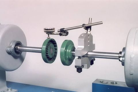
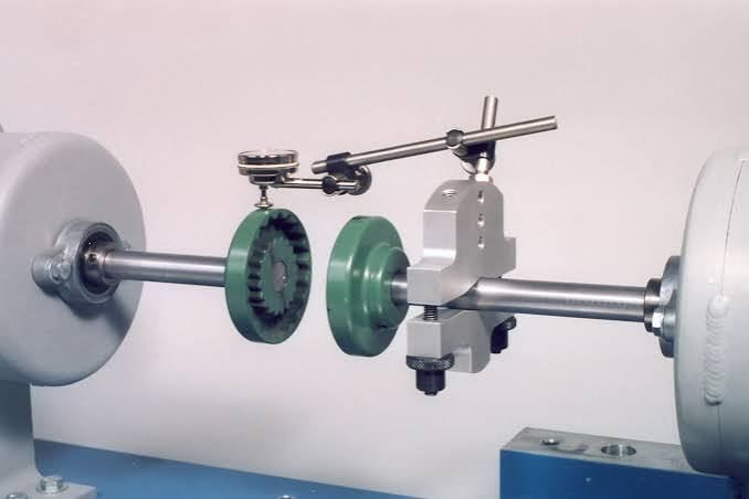
Dial indicators measure relative movement between components as a shaft is rotated. They can be used for coupling alignment, bearing measurements, and other mechanical alignment procedures.
Shaft Sag Measurement Equipment
Shaft sag measurement tools are used to account for the natural deflection of long shafts or measurement bars under their own weight. Correcting for sag can be important when interpreting alignment measurements.
Electronic Measurement Systems
Electronic alignment systems use sensors and digital measurement units to capture shaft positions. Data can be transferred to software for analysis, documentation, and comparison.
Main Components of Alignment Systems
| Component | Function |
|---|---|
| Laser transmitter | Generates the alignment reference beam |
| Measurement sensor | Detects laser position or shaft movement |
| Brackets | Hold sensors and measurement devices |
| Targets | Provide reference points for optical measurements |
| Dial indicators | Measure mechanical displacement |
| Digital display | Shows measurement data |
| Alignment software | Processes and analyzes measurements |
| Shaft fixtures | Attach equipment to the shaft |
| Reference supports | Establish stable measurement points |
| Calibration equipment | Verifies measurement accuracy |
Factors Affecting Marine Shaft Alignment
Shaft Length
Long propulsion shafts can experience measurable deflection under their own weight. Shaft length therefore affects measurement and alignment calculations.
Bearing Arrangement
The number and position of bearings influence shaft support and load distribution. Changes in bearing elevation or position can affect the alignment condition.
Hull Deformation
The vessel's hull can change shape due to loading, temperature, water conditions, and structural effects. Alignment may therefore need to account for the vessel's specified condition during measurement.
Temperature
Machinery components can expand as they reach operating temperature. Thermal growth between the engine, gearbox, bearings, and shaft line can affect the operating alignment condition.
Shaft Weight
Heavy shafts can deflect between supports. This effect needs to be considered when measuring long shaft trains.
Propulsion System Design
Engine type, gearbox configuration, shaft diameter, bearing locations, stern tube arrangement, and propeller characteristics all influence alignment requirements.
Marine Shaft Alignment Process
A typical alignment procedure can include the following stages:
- Review engineering drawings and alignment specifications.
- Inspect shafting, bearings, couplings, and related components.
- Establish the required reference system.
- Install measurement brackets and sensors.
- Take measurements at specified positions.
- Apply required corrections for shaft sag and other measurement effects.
- Analyze vertical and horizontal alignment.
- Adjust relevant machinery or bearing positions.
- Repeat measurements.
- Document the final alignment condition.
Actual procedures vary according to vessel design and manufacturer requirements.
Applications of Marine Shaft Alignment Equipment
Commercial Ships
Cargo ships, container vessels, bulk carriers, and other commercial vessels use propulsion shaft systems that require controlled alignment during construction and maintenance.
Naval Vessels
Naval propulsion systems can involve complex shaft trains and strict engineering requirements. Specialized alignment procedures may be used during construction, overhaul, and maintenance.
Passenger Vessels
Cruise ships, ferries, and other passenger vessels can use alignment equipment during propulsion system installation and inspection.
Workboats and Offshore Vessels
Tugs, supply vessels, service vessels, and other workboats may require shaft alignment inspection as part of propulsion system maintenance.
Shipyards
Shipyards use alignment equipment during vessel construction, machinery installation, shaft-line assembly, and repair work.
Alignment During Vessel Construction
During new vessel construction, shaft alignment can involve multiple stages. Machinery foundations, stern tube components, bearings, couplings, and propulsion equipment must be positioned according to the engineering design.
Alignment measurements can be repeated as major components are installed because changes in structure or equipment position can affect the shaft line.
Maintenance and Inspection
Regular inspection can help identify changes in shaft alignment during a vessel's operating life. Indicators such as abnormal vibration, bearing temperature changes, coupling problems, or seal leakage may prompt further alignment investigation.
Measurement equipment should also be maintained and verified. Laser units, sensors, brackets, digital instruments, and mechanical gauges should be inspected for damage and checked according to manufacturer instructions.
Benefits of Digital Alignment Systems
Digital marine shaft alignment equipment can simplify measurement collection and data analysis. Depending on the system, it may provide:
- Real-time measurement displays
- Automatic calculations
- Horizontal and vertical alignment data
- Measurement records
- Graphical alignment reports
- Data storage
- Repeatable measurement procedures
These features can help reduce manual calculation and make alignment results easier to document.
Safety Considerations
Marine shaft alignment work can involve heavy machinery, rotating equipment, elevated loads, confined spaces, and electrical or laser-based instruments.
Equipment should be installed securely, and machinery should be isolated before personnel work around rotating components. Lifting operations should use appropriate procedures and equipment.
When laser systems are used, personnel should follow the applicable laser safety requirements and avoid direct exposure to the beam.
FAQs
What is marine shaft alignment equipment used for?
Marine shaft alignment equipment measures the position and angular relationship of propulsion shafts, bearings, couplings, engines, gearboxes, and other components in a vessel's propulsion system.
How does laser shaft alignment work?
A laser transmitter establishes a reference beam while sensors measure the beam position at selected shaft locations. Software can then calculate shaft offsets and angular alignment.
Why is shaft alignment important on ships?
Alignment affects how loads are distributed through bearings, couplings, shafts, and connected machinery. Proper alignment according to the engineering specification helps support reliable propulsion system operation.
What can cause marine shaft misalignment?
Potential factors include incorrect installation, bearing movement, hull deformation, thermal expansion, shaft deflection, machinery movement, and changes in structural conditions.
How is marine shaft alignment verified?
Alignment is verified by taking measurements at specified points, analyzing shaft position and angularity, making necessary adjustments, and repeating measurements to confirm the final condition.
Conclusion
Marine shaft alignment equipment provides measurement and analysis tools for positioning propulsion shafts and related machinery. Laser systems, optical instruments, dial indicators, electronic sensors, and specialized fixtures can be used to assess shaft offsets, angularity, bearing positions, and coupling relationships.
The alignment process requires consideration of shaft length, bearing arrangement, hull condition, thermal effects, shaft weight, and propulsion system design. Careful measurement, appropriate corrections, repeated verification, and proper documentation help establish the shaft alignment specified for a particular marine propulsion system.