How Valve Actuation Systems Work: A Complete Guide
Valve actuation systems are mechanisms used to open, close, or position valves in fluid-handling and process systems.
They convert an energy source into mechanical movement, allowing a valve to regulate the flow of liquids, gases, steam, or other process media.
Depending on the application, valve actuation can be performed using pneumatic, electric, hydraulic, or manual mechanisms. Automated systems can also connect actuators with control equipment to coordinate valve movement with process conditions.
What Are Valve Actuation Systems?
A valve actuation system consists of an actuator and associated components that move a valve to a required position. The actuator may rotate a valve stem or produce linear movement depending on the valve design.
For example, quarter-turn valves such as ball and butterfly valves generally require rotational movement, while some gate and globe valve configurations use linear movement.
The actuation system may operate the valve between fully open and fully closed positions or hold it at intermediate positions for flow regulation.
How Valve Actuation Systems Work
Although designs vary, most valve actuation systems follow a similar operating sequence.
1. Control Signal
The process begins with a command from an operator, control panel, programmable logic controller, distributed control system, or another control device.
The signal specifies the required valve position or operating action.
2. Energy Conversion
The actuator receives an energy source and converts it into mechanical movement.
Pneumatic actuators use compressed air, electric actuators use electrical energy, and hydraulic actuators use pressurized fluid.
3. Mechanical Movement
The actuator produces either rotational or linear movement. This movement is transferred through an actuator shaft, coupling, linkage, or stem connection.
4. Valve Positioning
The movement changes the valve position. Depending on the valve design, this can open a flow passage, restrict flow, or stop flow completely.
5. Position Feedback
Many automated systems include position sensors or switches that indicate whether the valve is open, closed, or at an intermediate position.
This information can be sent to the control system for monitoring and process coordination.
6. Final Control
The control system can continuously adjust the actuator position when the application requires modulating flow rather than simple open-or-close operation.
Main Types of Valve Actuation Systems
Pneumatic Valve Actuation Systems
Pneumatic actuators use compressed air to create mechanical movement. They are commonly used in industrial environments where compressed-air infrastructure is available.
Pneumatic actuators can provide relatively rapid operation and are available in configurations designed for both rotary and linear valves.
Electric Valve Actuation Systems
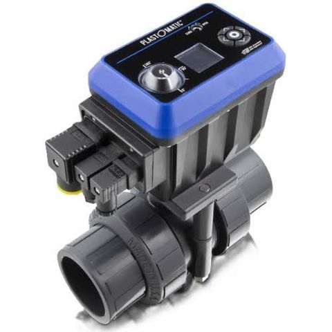
Electric actuators use an electric motor and mechanical transmission system to move the valve. They can be integrated with electrical control systems and position feedback devices.
Electric actuation is used across water treatment, manufacturing, energy, HVAC, and process control applications.
Hydraulic Valve Actuation Systems
Hydraulic actuators use pressurized fluid to generate movement. They can produce high mechanical force and are used in applications involving large valves or demanding operating conditions.
Hydraulic systems require appropriate fluid circuits, pumps, valves, and control components.
Manual Actuation
Manual systems use handwheels, levers, or other mechanical arrangements. They do not normally require an external power source.
Manual actuation can be appropriate for valves that are adjusted occasionally or located in accessible areas.
Electro-Hydraulic Systems
Electro-hydraulic systems combine electrical control with hydraulic movement. An electrical signal controls hydraulic components, which then generate the force required to move the valve.
These systems can be used where precise control and substantial actuator force are required.
Comparison of Actuation Types
| Actuation Type | Energy Source | Movement | Typical Characteristics |
|---|---|---|---|
| Pneumatic | Compressed air | Rotary or linear | Rapid operation |
| Electric | Electrical power | Rotary or linear | Easy electrical integration |
| Hydraulic | Pressurized fluid | Rotary or linear | High force capability |
| Manual | Human input | Rotary or linear | Simple operation |
| Electro-hydraulic | Electricity and hydraulic fluid | Rotary or linear | Integrated control and high force |
Main Components of Valve Actuation Systems
Actuator
The actuator generates the mechanical force required to move the valve. Its design depends on the required torque, thrust, travel, and operating conditions.
Valve Stem Connection
The connection transfers actuator movement to the valve stem or shaft. Proper alignment is important for reliable movement.
Power Supply
The power source depends on the actuator type. Pneumatic systems require compressed air, electric systems require electrical power, and hydraulic systems require pressurized fluid.
Control Unit
A control unit receives commands and regulates actuator operation. It may include switches, relays, electronic controllers, solenoid valves, or other control components.
Position Sensor
Position sensors provide information about valve movement and final position. This feedback can help control systems verify whether the valve has reached the intended state.
Limit Switches
Limit switches detect specific valve positions, commonly fully open and fully closed conditions.
Manual Override
Some automated actuators include manual override mechanisms that allow operators to move the valve when the primary energy source is unavailable.
Factors Affecting Actuation System Selection
Several factors should be evaluated before selecting a valve actuation system.
Valve Type
Ball, butterfly, gate, globe, plug, and other valves have different movement requirements. The actuator must match the valve's operating mechanism.
Required Torque or Thrust
Rotary valves generally require torque, while linear valves require thrust. The actuator must generate sufficient force throughout the valve's operating range.
Operating Environment
Temperature, humidity, dust, corrosive substances, outdoor exposure, and hazardous-area requirements can influence actuator selection.
Operating Speed
Some processes require rapid valve movement, while others need slower and controlled positioning.
Modulating Requirements
An on-off application may require only two defined positions. Flow-control applications can require continuous positioning and feedback.
Available Energy
The availability of electricity, compressed air, or hydraulic power can influence which actuation method is practical.
Applications of Valve Actuation Systems
Water and Wastewater Treatment
Actuated valves can control water movement through filtration, pumping, treatment, storage, and distribution processes.
Oil and Gas Processing
Valve actuation systems can control the movement of fluids through pipelines, processing equipment, storage systems, and other infrastructure.
Chemical Processing
Automated valve systems can regulate the movement of process chemicals and support controlled process sequences.
Power Generation
Actuated valves are used in systems involving cooling water, steam, fuel, condensate, and other process fluids.
Manufacturing
Industrial plants use valve actuation for process water, compressed air, gases, chemicals, and other fluid-handling systems.
HVAC Systems
Actuated valves can regulate chilled water, hot water, steam, and other fluids used in heating and cooling systems.
Automation and Control
Modern valve actuation systems can be integrated with PLCs, SCADA platforms, distributed control systems, and industrial communication networks.
Sensors can provide information about valve position, actuator status, operating cycles, and selected process conditions. This allows control systems to coordinate valve movement with pumps, tanks, compressors, heat exchangers, and other equipment.
Digital monitoring can also help identify abnormal movement, incomplete positioning, or repeated operating cycles.
Maintenance of Valve Actuation Systems
Regular maintenance helps maintain reliable actuator and valve operation. Inspection procedures may include checking electrical connections, pneumatic or hydraulic lines, mounting hardware, valve-stem connections, seals, position indicators, and control components.
Pneumatic systems should be checked for air leaks and pressure irregularities. Electric actuators may require inspection of wiring, switches, motors, and control components. Hydraulic systems should be examined for fluid leaks, pressure problems, and hose or fitting deterioration.
Maintenance intervals should follow the equipment manufacturer's instructions and the operating conditions of the installation.
Safety Considerations
Valve actuation systems can operate under electrical, pneumatic, hydraulic, thermal, or process pressure hazards. Appropriate isolation procedures should be followed before inspection or maintenance.
Workers should verify that the valve and actuator are isolated from hazardous energy sources before accessing moving or pressurized components. In hazardous environments, actuator and electrical equipment should also meet the applicable area classification requirements.
Frequently Asked Questions
What is the purpose of a valve actuation system?
A valve actuation system provides the mechanical movement needed to open, close, or position a valve in a fluid-handling or process system.
What are the main types of valve actuators?
The main types include pneumatic, electric, hydraulic, manual, and electro-hydraulic actuators.
How do pneumatic valve actuators work?
Pneumatic actuators use compressed air to generate movement. The resulting rotary or linear motion is transferred to the valve mechanism.
What is the difference between rotary and linear actuation?
Rotary actuation produces angular movement and is commonly used with ball, butterfly, and plug valves. Linear actuation produces straight-line movement and is used with various gate and globe valve configurations.
Why is position feedback important?
Position feedback allows a control system to determine whether the valve has reached the intended position. It can support automated sequencing, monitoring, and process control.
Conclusion
Valve actuation systems provide the mechanical link between control commands and valve movement. Pneumatic, electric, hydraulic, manual, and electro-hydraulic technologies can be selected according to valve design, force requirements, operating speed, available energy, environmental conditions, and control needs.
The actuator, valve connection, power source, control unit, sensors, and related components work together to provide controlled valve positioning. When properly selected, installed, monitored, and maintained, these systems can support fluid handling and automated process operations across many industrial applications.